CAPSTONE BLOG #8: 4/13/24
During the work period of March to April, the team made significant improvements by optimizing the clamp's performance. One way the team accomplished that was by increasing the size of the cam (located next to the white knob) to increase the clamp opening angle as shown in Figure 1. Furthermore, the team was able to conduct a validation test from which we'll share some key takeaways later on. Nevertheless, in this blog, the team will share updates made to the design and an optimized design was created based on the validation results.
Proceedingly, the team will share the progress and major milestones that have been achieved so far. The following figure shows the updated cam design that was proposed in the previous blog. Since then, the team printed the physical version shown below and increased the opening angle from 12˚ to approximately 33˚ successfully.

Figure 2 shows the clamp at an open angle once it comes in contact with the cam.

The two figures shown above display updates that were made which played an instrumental role for the team to successfully collect data during the validation phase. Increasing the cam size was necessary to increase the possibility for the top clamp to clamp onto the drawstrings of the trash bag. Furthermore, the retainers that were implemented in Figure 2 were necessary since the tying clamp with no retainer offered no chance, 0% success rate to be exact. The retainers pictured in the figure above played a vital role in positioning the drawstrings.
Figure 3 shows the clamped position that is achieved once the clamp revolves around the outer cam (which is located next to the white knob) one time.

Figure 3: Clamp after clamping drawstring
Figure 4 shows the previous clamp designs that have been 3D printed. It also shows a potential solution that the team will conduct validation within the upcoming days.


Figure 4: Previous Designs and Potential Solution
During the validation phase, the team conducted validation with several different clamps to determine which clamp was the most reliable. The two main determining factors were split up into two stages which were clamping the drawstring as shown in Figure 3, followed by the user finishing the knot. During this phase, the clamp located on the top right corner of Figure 4 had very low tension when testing and left a large amount of drawstring slack. However, it wasn't consistently clamping the drawstring to successfully tie the knot. From there, the team decided to print another clamp which would feature a drawstring retainer located in the middle as seen in the top left corner of Figure 4. This clamp performed the best with high tension, successfully clamping the drawstring and outperforming the other prototypes.
As a result, the team chose the middle clamp since it guaranteed the highest success rate at clamping the drawstrings. However, to further optimize the design of the clamp, the team is looking to conduct more validation with the clamp labeled as a potential solution. Team Lend-a-Hand is expecting the refined clamp to outperform the previous design by providing the ideal amount of tension while maintaining the clamping ability the middle-retainer clamp has.
Although the team achieved a 95% success rate during validation tests by successfully clamping the drawstring trash bag 19 times out of 20, the team has not met two goals. The 7-second to-clamp drawstring and 10 cm handle length goals. From the 20 trials conducted, the drawstrings were clamped under 7 seconds for only 25% of the time and at or over 10 cm of handle length 40% of the time. From this output, it is evident that there is a lot of room for improvement. For this reason, the team looks to improve the clamp-tying design with the potential solution shown in Figure 4.


Figure 5: Current Assembly compared to potential updated assembly
Furthermore, another key takeaway from validation results is that the team found greater success when the trash bag was removed from the trash can container and it was placed at the base of the tying assistant. This allowed for the tying clamp to be lowered to the lowest setting on the ratchet system. Which leads to the next point that should be made, the ratchet system was no longer necessary for this application since the trash bag was being removed from the container. Figure 5 shows an optimized design compared to what the current assembly is. The ratchet system allowed for the adaptability of containers that were different shapes or sizes, however, it was not used once the scope was slightly changed. However, it should be stated that removing ratchet system did yield for potential improvement in the design.
Mantenieks, Maris, et al. “Replacement Wastebasket.” KraftMaid, www.kraftmaid.com/replacement-wastebasket/.
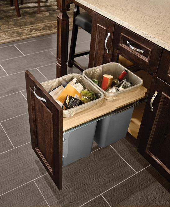
Figure 6: Sliding Cabinet mechanism
The device can be significantly reduced in size to where users or homeowners can have the device in a different location other than where the trash can container is located. An example of this would be placing the device under the sink or having it located on a cabinet that allows for it to slide out. Figure 6 shows a cabinet that can slide outwards. This can be used to mount the tying mechanism onto it instead of the trash container shown in the picture. This would also appeal for any users that wish to keep a seamless design in their kitchens.
Poster Draft:


Comments
Post a Comment