CAPSTONE BLOG #4: 11/25/2023
For the work period of November 11 - November 25 what work toward your team's project has been completed? Please provide a description of tasks that are completed, as well as tasks currently in progress.
From November 11th up to November 25th, Team 30 has established the tying mechanism design, established the design of the rest of the device, and analyzed individual device aspects for validation on the device’s intended movement. The team has also built up a Bill of Materials for the indented pieces of the solution (aluminum extrusions, wooden base, t-bolts, etc.) and held continued weekly meetings with the professor for technical advice on design review writing and the DR presentation slides. A visual of the tying mechanism, a clamp piece, is shown in Figure 1.
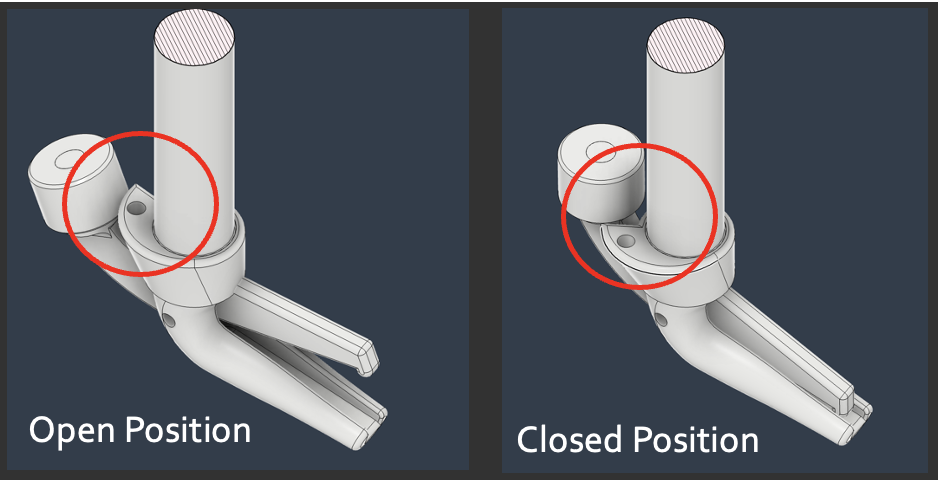
Figure 1: Demonstration of tying mechanism when open and closed
As the semester is coming to a close, the team is finalizing the dimensions for all of the mechanisms to ensure there are proper tolerances and no misalignments. Any required bolts and screws are in the process of being collected as these tolerances are found. To finalize the analysis, a tipping analysis is currently being done and will be our last form of analysis that will be presented for the report.
Provide a brief description of your final design and the key design features your team has created that address the main issues from your problem.
The final design for the Trash Bag Tying Assistant is a horizontal extrusion with 2 mechanisms along it. An upside down clamp attached to a rotating crank lever, and a hanging spring-loaded hook. These two mechanisms work together to put a trash bag drawstring in a position to be tied with one pull. The final position of the system is designed to mimic a human knot tying position, as shown in Figure 2.
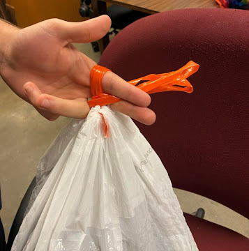
Figure 2: A “looped and clamped” position
To achieve the “looped and clamped” position that prepares an overhand knot, the spring-hook holds tension in the drawstring allowing the clamp’s rotation to catch it and wrap it around itself. The clamp then opens and bites on the drawstring, creating a pinch. From this position the user can pull the loop around the clamp to finish a knot.
Addressing the practicality and usability of one hand, the device operates using a single arm crank lever. The full device puts one end of the extrusion on a vertical stem like a cantilever beam. The vertical is placed on a square base as shown in Figure 3. The beam can be moved vertically along the stem to accommodate different trash can heights.
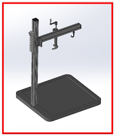
Figure 3: Full assembly of Trash bag tying assistant
In order to properly house some commonly used kitchen-sized trash cans, a base was constructed to accommodate trash cans with a length between 10.8 and 19.2 inches, a width between 9.75 and 18.7 inches. Additionally, with a base established for the device, it allows for vertical adjustability of the device as well as holding the extrusion, where the rotating clamp and spring-hook is held in place.
What are the key analytical results your team has at this point to demonstrate the successes and strengths of your current design?
The team has conducted analysis on the trash bag tying assistant by doing hand calculations to determine mechanism relationships.
The team analyzed that the drawstring tension is formed by and equal to the spring force. The team then calculated an ideal spring constant for the spring. The team formed equations to explain that the user’s torque on the clamp shaft should remain greater than the resistance torque applied by the drawstring and spring. These torque relations can be broken down into an inequality between user force input and spring constant.
Through research, the team chose 35 N for a “safe minimum” force value that most humans can output with their arms, and found that the spring k value should remain under 3,000 N/m [26,000 lbf/in], which is very gracious for this device and easy to maintain. A spring constant of k = 0.3 N/m [2.77 lbf/in] was chosen.
Cantilever beam calculations have also been conducted to determine the beam deflection on the horizontal arm of the tying assistant on which 18.1 N was determined to be the worst case scenario load with a maximum deflection of 0.12 millimeters as shown in Figure 4.
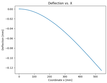
Figure 4: Cantilever Beam Analysis Graph
Looking forward to Capstone II, what preparations will your team have completed prior to the start of the Spring 2024 semester to be ready to execute your design?
Since the team was set back during preparation for the design review, Lend a Hand will spend the first part of the Winter 2023 break reanalyzing the shape and specifications of the device. That task will be completed before 12/16. Afterward, the team plans to order required pieces for the device and begin 3D printing by 12/20. Once the pieces have arrived, the team intends to begin assembly and execution/validation at the beginning of Capstone II. As everyone’s schedule will vary over the winter break, the team aims to meet once a week in order to stay on track for the second semester and avoid repeating the same mistakes with the setbacks that were incurred during the first semester.
Provide at least 3 figures to show the concrete progress and current status of the team's work. Please refrain from presenting your team's Gantt charts, catalog photos of parts/components you plan to use, or photos of acquired materials with no further work.


Comments
Post a Comment