CAPSTONE BLOG #5: 2/3/24
For the work period of December 11 - February 3, what work toward your team's project has been completed? Please provide a description of tasks that are completed, as well as tasks currently in progress.
During the work period, the majority of completed work included device redesigns and accumulation of materials. Over the winter break, the team made efforts to make sure that the entire device would work by the specifications that were established. Multiple decision reinforcements were made to improve the reliability of the device.
First, the clamp changed its design to have torsional springs (highlighted in blue) inserted between the inside and outside clamp as shown in Figure 1. This is to ensure that the clamp always closes to the default position after each rotation.

Figure 1: Clamp Torsion Springs Default (left) and Open (right) Positions
For the clamp to rotate as intended, bearings were placed between the outer and inner shafts. The bearing allows the inner shaft to rotate while the outer shaft remains fixed. This is ideal since the outer shaft secures the piece to the extrusion while inner rotates the clamp. Figure 2 shows the redesigned tying clamp and displays the cross-section of the clamp. The three arrows show the three locations where the bearings will be placed.
.png)

Figure 2: Tying clamp and cross-section of tying clamp
Another obstacle that the team encountered during the break was mounting the horizontal aluminum extrusion to the vertical extrusion through the linear bearing carriage. Since the carriage rides along the vertical extrusion, there was no space on the inside for attachment to the horizontal extrusion. For this reason, an adapter bracket made out of PLA was added to connect both the extrusion and carriage. Figure 3 shows how the adapter bracket is integrated into the design.
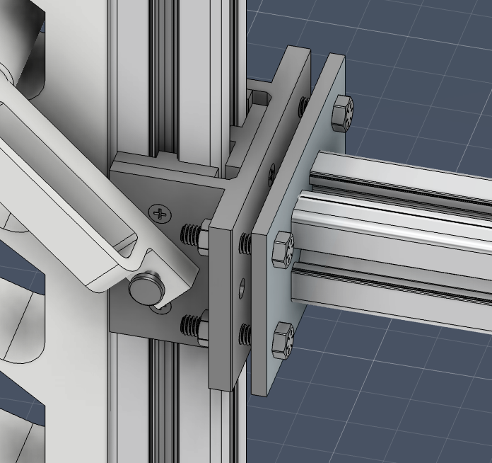
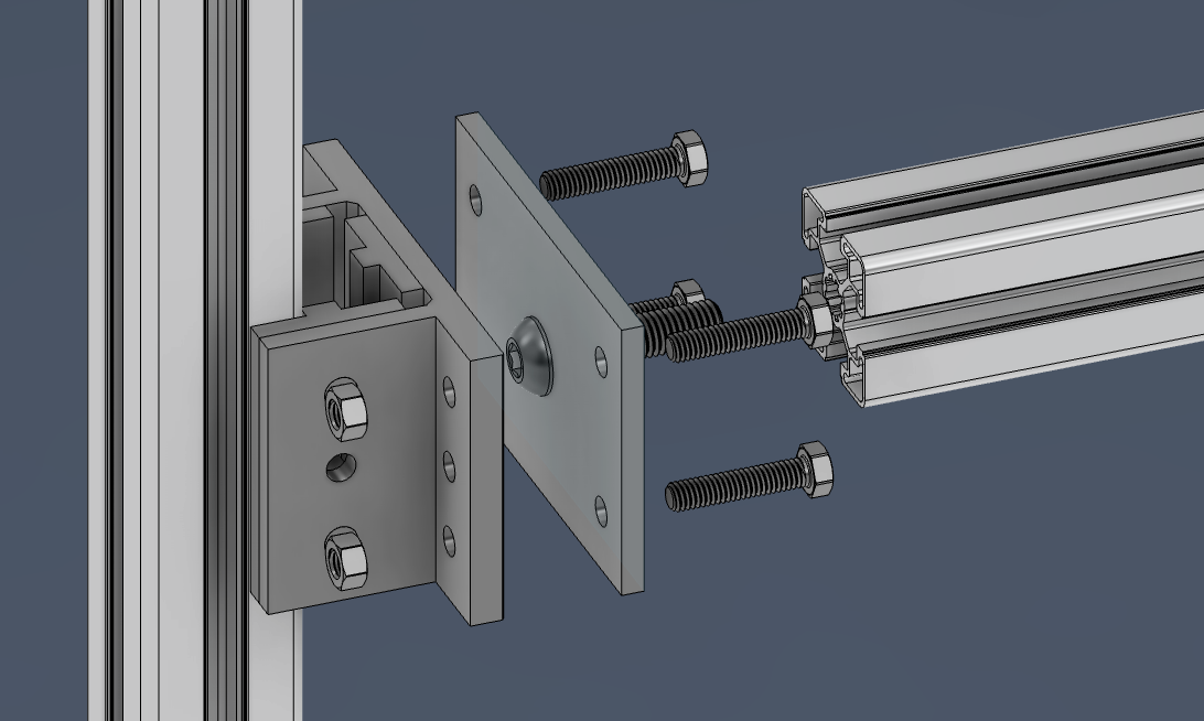
Figure 3: Adapter bracket for horizontal extrusion
Additionally, the ratchet mechanism responsible for adjusting the vertical height of the device was redesigned. To ensure that the mechanism fits scope, a secondary handle was designed and attached to the side. For the ratchet mechanism to function seamlessly, it now consists of an adjustable locking system with catch rods to allow the device to stay in place after the user modifies the height of the device. Figure 4 shows the comparison between the redesigned (right) and old (left) ratchet mechanisms.
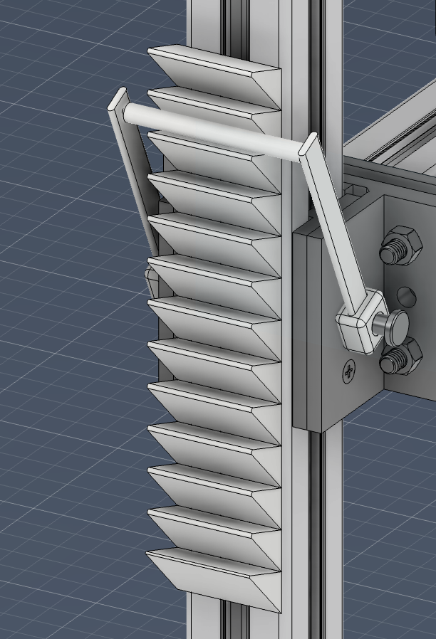
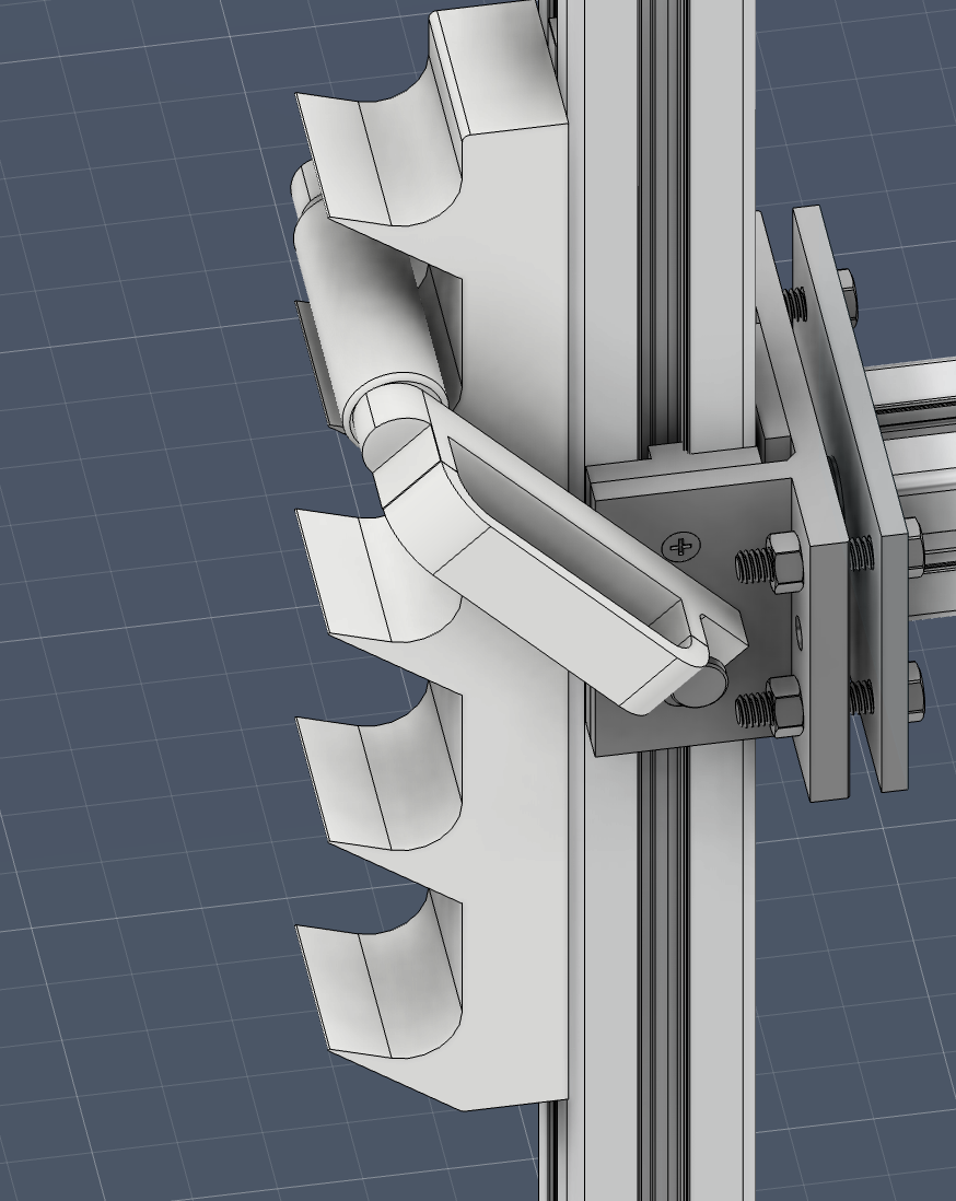
Figure 4: Previous design of ratchet mechanism and Improved design of ratchet mechanism
A retractable line system was developed as an improvement from the previous spring-hook. The original design supported a pinned extension spring, leaving an awkward-to-manipulate piece that would sway randomly and be in the way when not in use. Since the target user is a one-armed individual, the mechanism needed consistent positioning for practical use. The aforementioned coil spring and retractable line were introduced to ensure that the hook (present in both designs, catches drawstrings) would always return to the same initial position. Figure 5 shows a concept of the retractable line mechanism created by spare parts. Due to its practicality, the mechanism from Figure 5 is being considered for the device, and will be placed in a PLA casing to attach to the aluminum extrusion. The PLA casing for the retractable line is shown in Figure 6. The new system takes up less space and is overall more user-friendly for one-armed individuals.
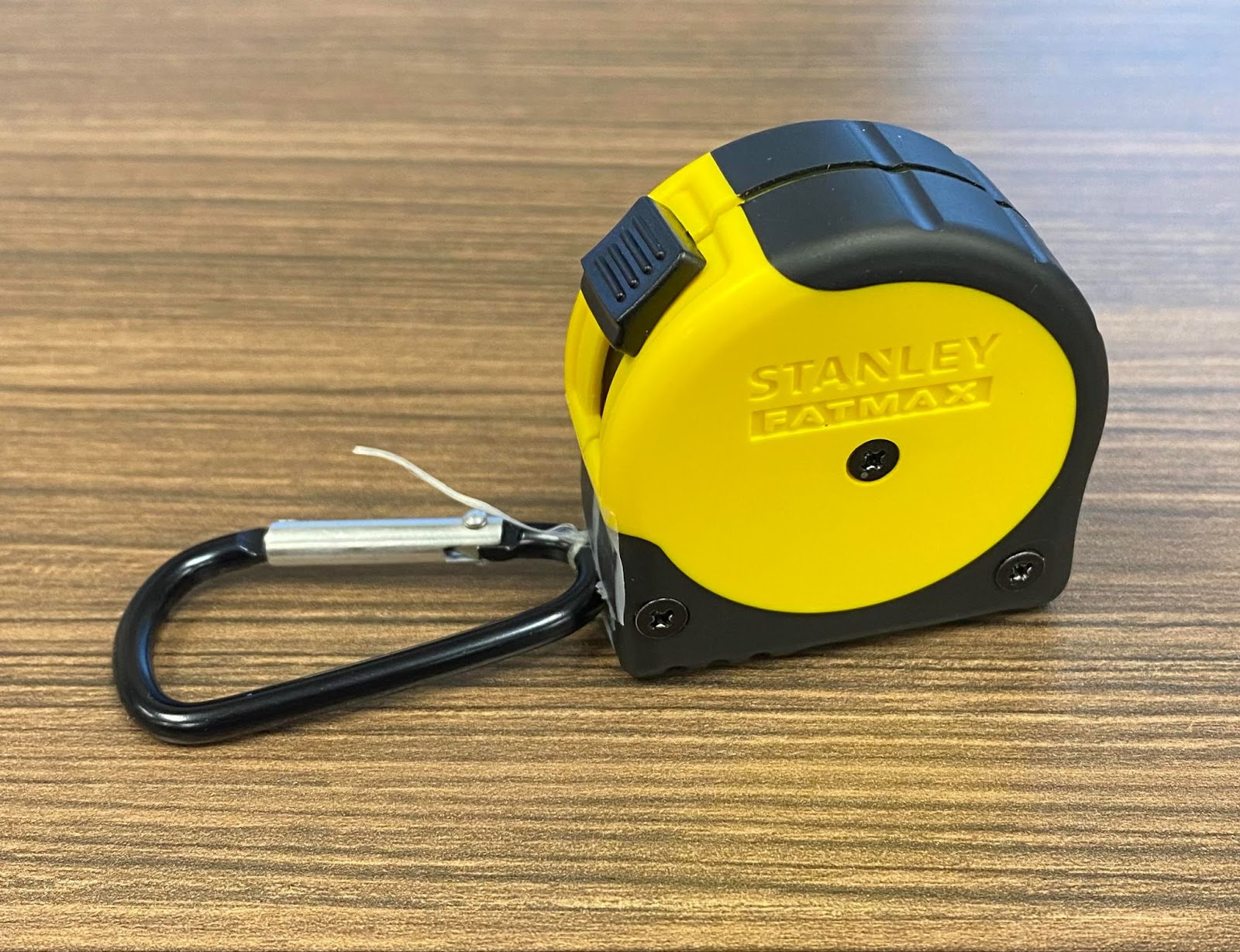
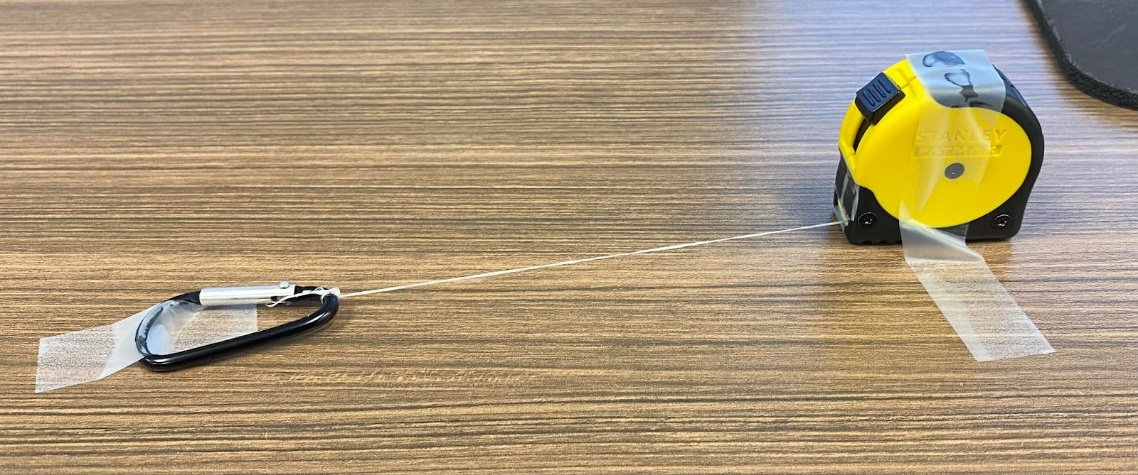
Figure 5: Retractable Line Mechanism Initial (top) and Extended (bottom) positions

Figure 6: Retractable Line Casing


Figure 7: Printing Progress on Ratchet System and Clamp
For the work period of February 4 - February 17, what is your team's plan for near term work? What major milestones does the team hope to achieve in your work?
Moving forward, in the work period of February 4 to February 17, the team aims to finish the prototype device and run initial validation testing. The first week will be spent assembling the prototype and gathering all validation tools. Once all device components have been acquired, the team will check the fitment of all parts and which parts such as screws or bolts don't fit as expected. The team will also obtain all remaining validation items like the remaining two trash cans, bag filling, and measurement tools. The team hopes to finish all of this by February 10th.
Once assembly is completed and the fitment of all parts are proper, the team will then begin the validation process. Validation will include but will not be limited to the use of 5 different trash cans, bags filled with items of varying weights, and the use of UH engineering tools such as a strain gauge. Validation will include verifying the position of components during operation of the device. Validation testing is aimed to occur from February 11-17.


Comments
Post a Comment